


Basic principle of fiber optic pressure sensor - News - Global IC Trade Starts Here Free Products
2021-05-02
In order to clarify the fiber optic Pressure Sensor, the basic principle of the fiber displacement sensor must be introduced. Figure 3-35 shows the principle of the fiber displacement sensor. It is a function of transmitting optical signals by using optical fibers; indirectly measuring the distance between the measured reflective surfaces according to the intensity of the detected reflected light. 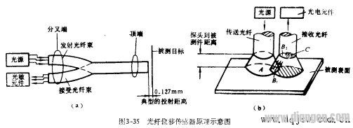
In a typical fiber displacement sensor, a fiber optic cable with a diameter of 0.762 mm is composed of 600 optical fibers. The inner core of the fiber is a flint glass with a refractive index of 1.62, and the cladding is a brand glass with a refractive index of 1.52. The end of the cable is divided into two branches, one for light emission and one for light reception. The light source is a 2.5V incandescent bulb, and the sensitive component that receives the optical signal is a photocell. An electrical signal is generated by the photosensitive detector that is proportional to the intensity of the received light. For a displacement of 0.25 m, a voltage output of 1 V is produced with a resolution of 0.025 um.
The working principle of the fiber displacement sensor is: when the fiber probe end is close to the technical test piece, the light in the transmitting fiber cannot be reflected into the receiving fiber, and the photocurrent signal cannot be generated; when the surface to be measured is gradually far away from the fiber When the probe is used, the area of the surface to be measured illuminating the surface of the transmitting fiber is getting larger and larger, so that the area of the corresponding emitting light cone and the receiving light-weighting table B1 is larger and larger, so that the B2 area of the receiving fiber end face is also brighter. The larger, there is an output signal that increases linearly with the displacement of the probe; when the entire end face of the receiving fiber is fully illuminated, the output signal reaches the displacement - the "light peak" on the output signal curve. The segment curve is called the front slope area; when the surface to be measured continues to move away from the probe, the area of B2 illuminated by the reflected light is larger than C (see Figure 3-36), that is, some of the reflected light is not reflected into the receiving fiber, and is received. The fiber is farther away from the surface to be measured, so that the received light intensity is reduced, so that the output signal of the photosensitive detector is gradually weakened, and then enters the back slope area of the curve, as shown in Figure 3-36. In the back slope area, the signal strength is inversely proportional to the square of the distance between the probe and the surface being measured. In the front slope of the displacement-output curve, the intensity of the output signal increases very quickly, so this area can be used to perform micrometer-scale displacement measurements; the back slope area can be used for distances with sensitivity, linearity, and accuracy requirements. In the so-called peak region, the sensitivity of the output signal to the change in light intensity is much greater than the sensitivity to displacement, so this region can be used to optically measure the surface state. 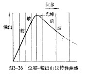
The arrangement of the illumination and receiving fibers is mainly as follows: random distribution, same-radio transmission, coaxial internal transmission, and half-distribution.
Fiber optic pressure sensors work like fiber displacement sensors. The light from the light source is transmitted from the optical fiber and projected onto the inner surface of the diaphragm, and then reflected, and then received by the receiving fiber and transmitted back to the photosensitive element, so that the position of the stock changes, and the output signal changes accordingly. In contrast to the fiber-optic displacement sensor, the small change in the position of the 腆 Dan is caused by the deflection of the diaphragm under the action of pressure, and the luminous flux is a function of the shape of the membrane and the average distance from the probe to the diaphragm.
JRT produced the high resolution optical distance measurement sensor for 16 years with lower cost. Our distance measuring sensor have small size, high accuracy.
The laser range finder components is characterized by an above-average measured value output frequency, up to 8hz. The miniature laser distance module is also suitable for monitoring defined distance and height during transport.
Distance Measuring Sensor, Accurate Laser Measuring Sensor, High Accuracy Distance Sensor, Optical Distance Sensors
UVW Signal Encoder Co., Ltd. http://www.rangesensors.com